Content:
Application note #11
Absolute values of reflectivity measurements with CT7a
To properly print this text, please download the file. You can easily do so using the Download button at the top right ↗️
Thank you for your interest!
Application note #11
Absolute values of reflectivity measurements with CT7a
Copyright:
Author:
Daniel Malaise, Dr Sc
First issue: October 2019
Last review: August 2020
This document is the sole property of OPO and, except to learn about our work, may not be used without our written consent.
Introduction
This note discusses how “absolute” values of the reflectivity of a coated mirror are obtained .For most work, relative measurements seem sufficient in order to monitor the degradation of the coating with exposure and decide when to clean it or replace it. But this situation is not satisfactory for two reasons:
- Each observatory develops its own standard and lives with it; inter-comparisons are difficult because there is no standard. The situation is similar to the one prevailing in Middle Age with units: a five league distance was not the same if the league was ‘Imperial’ or ‘Spanish’ or French’!
- In the same observatory, if the reference drifts, all measurements are drifting without any means to recognize it.
This is why absolute measurements are justified and we give, in this note, the way of achieving it.
This paper describes two ways of obtaining finally the values of absolute reflectance on site with a handy (portable) reflectometer .
- Indirect or comparative measurements using CT7 and a reference gauge.
- Direct absolute measurements using the new CT7a .
Structure of a comparison reflectometer
It is important to know that a comparison reflectometer does not actually “measure” the reflectivity of a sample mirror but compares the reflectivity of the sample mirror to the reflectivity of a gauge or reference mirror. The complete measurement “assumes” that the reflectivity of the gauge is known by an independent experiment.Precisely, the reflectometer tells: “if the gauge has a reflectivity of 87.5% at that wavelength, then the sample mirror has a reflectivity of 88.8%” at that same wavelength.
The final answer can be wrong for three reasons:
- The reflectivity of the gauge is not actually 87.5% but 86.3% or any other value.
- The measurement of the reflectometer does not repeat from one measurement to the other so that if you were to repeat the complete measurement (gauge then sample) several times, you would get different answers: 87.5%; 87.9%, 86.8% 87.2% ...
- The reflectometer is not linear in the range of measurements.
Here, one should at once notice another difficulty of such comparison. The reflectivity of coated mirrors varies with the position of the measuring spot on the mirror. This variation is an indication of poor coating; it can reach values of several percent if the mirror has been exposed. Here, we encounter two schools: the one that utilizes a small analysis spot (4 to 6 mm diam.) and the one that uses as large as possible analysis spot diameter. The argument of the latter is that with a small spot, you need a large number of measurements to reach a representative average value of the reflectance. This argument is weak because it has the immediate drawback of “hiding’ a poor quality coating; moreover, the number of measurements necessary anyhow for measuring properly the average reflectance is always sufficient to yield a significant value when utilizing a small spot.
The indirect or two step method for obtaining the absolute reflectivity of a sample mirror comprises of:
- Measuring the absolute reflectivity of a dedicated gauge or reference mirror.
- Comparing the reflectivity of the sample mirror with the reflectivity of the gauge, using an apparatus called ‘reflectometer’ that has two essential properties: - it is stable and repeatable ; - it is linear in the region where it is used (for instance better than 0.1% between 50% and 100% reflectivity for a mirror reflectometer.
One could ask why the technique for measuring the absolute reflectivity of the gauge cannot be directly utilized to measure the sample mirror. The reason is that one wishes to be able to measure any ‘sample mirror’: flat, curved, large, small; and sometimes in acrobatic positions. The absolute measurement of the gauge requires very special conditions mainly on the size of the gauge and is not compatible with field measurement of telescope mirrors.
We turn to the description of this two-step procedure of absolute measurement.
The comparison reflectometer
Fig. 1 shows the essential structure of the Comparison reflectometer. The light source is a Led or a combination of Led’s if several wavelength bands are required. After proper baffling (not represented), the central beam is split by an uncoated thin sheet of glass (BS). The reflected beam is directed onto the reference detector Dr through the stop Sr. The transmitted beam is directed through a well baffled collimator (ColSource) to the sample mirror and reflected back to the detector collimator. At the focus of the lens; a stop (Ss) defines the acceptance angle of the reflectometer by suppressing the scattered light at an angle larger than atan(r/f) where r is the radius of the stop and f the focal length of the lens. The detector Ds picks up the reflected beam.The two detectors are identical as well as the front-end electronics. The latter is composed of a trans- impedance amplifier and an A/D converter. Finally, the digital signal s is divided by the reference signal r and multiplied by the calibration factor cal to obtain the reflectivity:
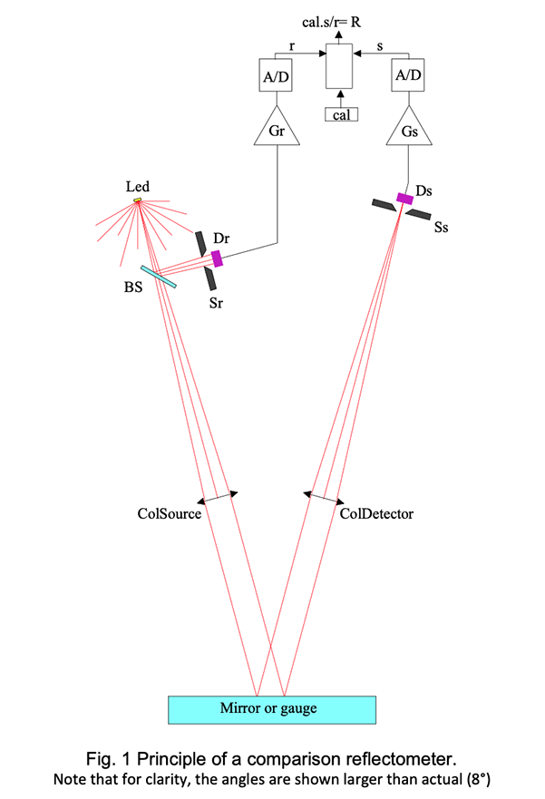
The calibration factor is obtained by measuring a gauge that has a known reflectivity Rg giving the measurement result: Rg=cal*s g /r g from equ (1) and hence cal=Rg*r g /s g .
The stability of the comparator requires that (Ds*Gs)/(Dr*Gr)= constant.
This condition can be fulfilled with great accuracy, but the balance of the detectivity of the two detectors when the temperature varies is not that simple. Currently we apply a linear temperature correction to each channel. The correction is usually of the order of a few hundredth of a percent but can reach one or two tenth of a percent. We select the detectors since 2016.
The stability of the measurement requires also that in the optical path :
(BS
t
*Ω
col
*T
L1
*T
L2
)/(BS
r
*Ω
sr
) = constant
BSr and BSt are the transmission and reflection of the beam splitter; Ω col is the output solid angle of the collimator; T L1 and T L2 are the transmissions of the two lenses and Ω sr is the solid angle opening of the reference stop Sr.
This condition on the optical balance of signal and reference paths is easy to fulfil down to an accuracy of about 1%; reaching better accuracy (stability) becomes very difficult when approaching the 0.1% limit.
Without much details, here is a list of difficulties in increasing order of magnitude :
- Mechanical stability of the mounts, especially when the temperature varies.
- Cleanliness of the optical elements (BS, L 1 and L 2 ); this is a very important issue.
- Equality of Ω col and Ω sr
- Polarization stability of the Led’s.
Relative measurements of reflectivity
Fig.2 shows a recording of reflectivity measurements in seven channels obtained with the new configuration of the CT7 . It represents measurements every 5 min during 69 hours. All channels were calibrated at 100% for ease of reading the results on the same scale; the temperature in °C has been divided by 10 and brought around 100 by adding a constant.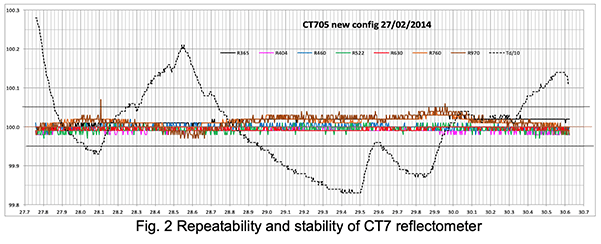
One sees that the repeatability, i.e. the variation from one measurement to the next is better than 0.01% except for the 970 nm channel. The three-day stability is much better than 0.05% for a temperature variation of 4.5°C.
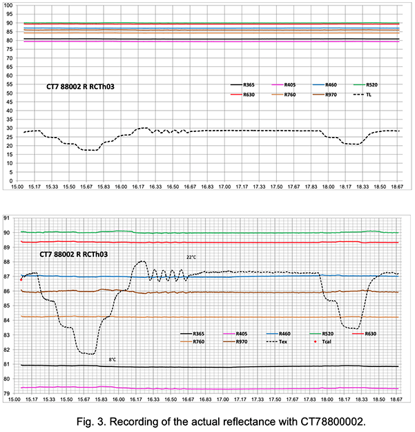
The lower diagram in Fig. 3. is the ordinate expansion of the upper one. One sees that over three and a half days and a temperature variation of 13°C, the stability is better than +/-0.1% for all channels and better than 0+/-0.05% for the deep red, red and blue channels, including the phases of fast temperature variations.
Note also that the largest departures take place with a lag when the temperature goes up. We suspect that this is due to starting nano condensation on the optical elements (including sample mirror). One should avoid performing precision measurements of reflectivity in conditions of raising temperature (here the rate was 1°C/15 min.)
We now turn to the description of the absolute measurement of the reflectivity Rg of the gauge. This is done in a dedicated instrument using a technique due to Strong and commonly called VW technique ; it will soon be clear why. Fig. 4a and 4b show the structure and operation of the VW measurement.
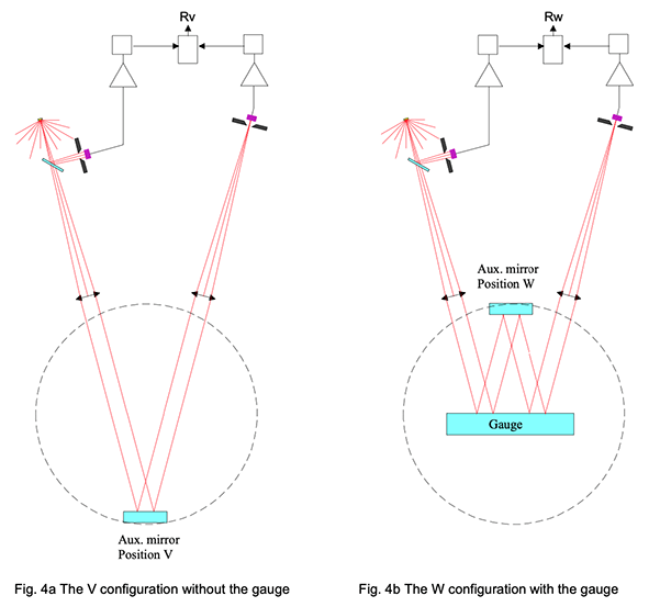
The operations are the following: An auxiliary mirror (Aux. mirror) is mounted on a rotation drum with two pre-set fixed positions at 180° from each other; the lower position (V) and the upper one (W).
On top of the instrument, one recognizes the elements of the reflectometer which are permanently fixed to the VW jig.
The measurement in Position V yields a reflectivity measurement Rv .
The auxiliary mirror being turned in the upper position, the unknown gauge is introduced so that its reflecting surface is parallel to the auxiliary mirror and contains the rotation axis thereof.
A second measurement in this W configuration yields a reflectivity measurement Rw .
Now observe that the path of the beam in this second measurement is exactly the same as it is in the first one except that the beam is reflected twice on the gauge. It follows immediately that the ratio between the second measure and the first one is equal to the square of the gauge reflectivity, independently from the unknown reflectivity of the auxiliary mirror. Hence
Rg = sqrt(Rw/Rv)
A thorough study of the errors due to small misalignments shows that it is easy to obtain a very accurate setting and, if the repeatability of the measuring part, i.e. of the CT7 is excellent, the absolute accuracy obtained is comprised between 0.1% and 0.5%.
It must be noticed however that the VW jig uses two areas of the gauge symmetric with respect to the center, while the CT7 uses the central part of the gauge. It is then mandatory that the gauge be of high quality concerning the uniformity of the coating. The error there should not exceed 0.02%, as long as the gauge remains clean and unscratched.
The instrument does not need to be calibrated but it is practical to run a calibration in the V configuration, setting all the calibration reference to 100%. Then measuring in the W configuration yields the simpler result:
Rg = sqrt(Rw)
Results of absolute measurements
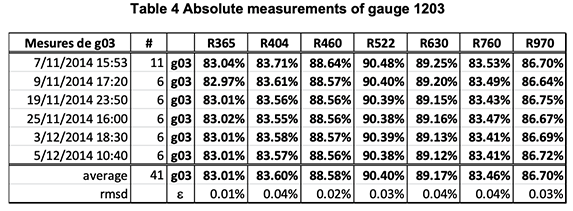
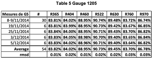
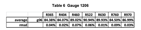
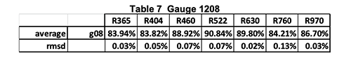
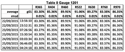
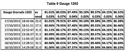
Hereunder, follows several examples of absolute calibration of gauges.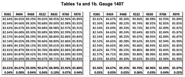
The two tables show two series of 10 measurements made with the calibrator on the gauge G1407. The last two lines are the average and RMS deviation of the ten measurements.
One sees that the global absolute accuracy is in the range of +/-.05% on all channels.
Note, however, that one records, on the same G1407, reflectance gradients three times as large (0.15%) over an area of 1 square cm.
CT7a: the absolute version of CT7
CT7a the absolute reflectometer
The natural step after developing the CT7 and VW absolute calibration jig was to combine the two apparatus in a single handy instrument. So that we can represent the two schemes of measurements as follows:The clear advantage of CT7a is that it utilizes an internal “arbitrary” reference for measuring in two steps:
- Measurement with the reference in the optical path: M r = I.R r
- Measurement with both the same reference and the sample mirror in the optical path: M s = I.R r .R s
- Computing the ratio of the two measurements: R s = M s /M r
One sees that the reference reflectivity R r cancels out of the algorithm and does not need to be known.
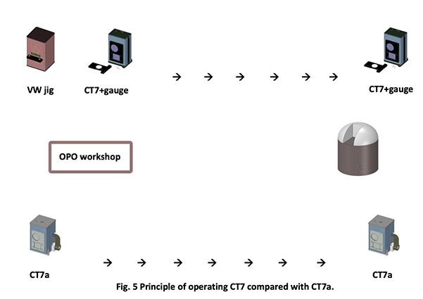
The difficulty is that in the standard VW scheme, the sample mirror is inside the instrument; that is clearly impossible when measuring a telescope mirror. One has to modify the optical path in order to bring the measurement point outside the instrument; this is obtained with a “ square root ” configuration as illustrated hereunder.
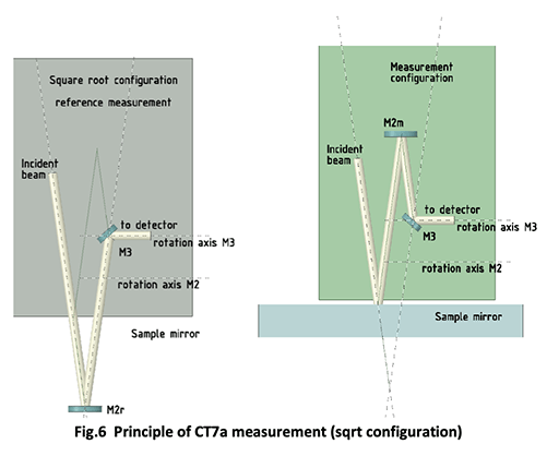
One sees that there are two axes of rotation; one for the reference mirror M2 which is in position M2r when performing the reference measurement, and in position M2m when performing the measurement on the sample mirror. The mirror M3 rotates around a second axis in order to bend the beam into the detector’s optical system. The two rotations are to be exactly 180° and repeatable; this constitutes the main difficulty added to the CT7 in order to generate absolute measurements.
Everything else is identical in CT7 and CT7a ; hence, the latter inherits the accuracy, stability and repeatability of the former. The interface is identical also, operating with a PC console or self-standing.
In practice, a measuring session with CT7a will be held as follows: rotate the reference mirror in the down position; perform one measurement; rotate the reference mirror in the upper position; perform as many measurements as planned. If at any time you have any doubt about the stability or if you want to do a test of stability, rotate the reference mirror back into the down position; perform one measurement; rotate the reference mirror in the upper position; perform the measurements as needed; compare the results.
The simplicity of the measuring process, the permanent possibility of checking its accuracy in situ, and the non-sensitivity to pollutions are the main arguments speaking for the absolute version of the CT7 .
Specifications of CT7a
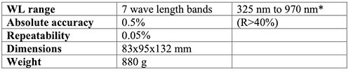
*7 bands can be chosen in the interval; we currently suggest: 365; 411; 528; 630; 750; 850; 940.
Other way of obtaining the absolute value of Rg
Usually, the gauge or reference mirror is measured in a separate laboratory. The most often used method is similar to the VW method described here above.The source is a spectrograph such as a CaryV with a special fixture reproducing the VW configuration (Fig. 7). A variation of this configuration consists in using a ‘pocket’ spectrometer as detector, and to illuminate the VW system with a collimated ‘white’ source.
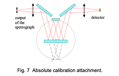
These configurations do not give an absolute accuracy better than +/-2% because one has to run through the spectrum first in configuration V and then in configuration W, then make the ratio between the two recordings; the time elapsed between the two measurements is therefore 50 to 100 times larger than with the CT7 . The system does not allow using modulation and digital lock-in detection which gives the CT7 its stability and repeatability approaching the 0.01%.
The wavelength range is limited to the source spectral output, combined with the spectrograph range, i.e. 450nm to 900 nm at most.
Another drawback is that the angles of the bundle with the gauge is usually much greater than 8° so that the method is prone to be sensitive to polarization and to interferometric effects if the mirror is coated for protection. The large angles result in a larger distance of the two spots on the gauge so that it must be large and very uniform.
Finally, one obtains the monochromatic reflectivity, and in order to use the gauge for calibrating a handy reflectometer , one must convolute the reflectivity with the band intensity of the reflectometer source. The latter is usually a LED and one cannot use the ‘effective’ wavelength of the latter instead of the convolution when one wants to reach an overall accuracy of 0.5%.
All these error contributors are drastically reduced in the method we have proposed in the first part of this note:
- Measurements in the two configurations are done within less than one minute with an instrument showing stability of the order of 0.02% per hour.
- The same beam and the same source are used in measuring the absolute reflectivity of the gauge and calibrating the reflectometer with the gauge.
- The used part of the gauge is quite small and easily made and maintained uniform.
- The angle of incidence is 8° on both the absolute calibration jig and the reflectometer so that one has not to take care of problems due to polarization or to thin layer interferometric effects.
Of course all the advantages of the CT7 + gauge comparison method are combined with the advantages of the VW absolute calibration method in the new CT7a ; this seems to be the top of the technical achievement.
For geometrical reasons, the number of simultaneous bands that can be measured in one CT7 apparatus is seven; if more bands are needed, one has to use two instruments with seven bands each.
The ultimate UV wl we strongly suggest with the CT7a is 365 nm. The regular CT7 can operate detectors which goes as low as 308nm with excellent results (only in reflectance mode), we call this the " Cherenkov version " of the CT7. We are still working on lower bandpaths.
It is also possible to extend the wavelength range into the near IR; this needs a modification of the apparatus because it uses PbS detectors and we can provide a three wavelength source: 1.05 μm; 1.5 (or 1.7) μm and 2.02 μm.
Scattering measurement
The relative scattering measurement is pretty the same as the relative reflectivity measurement. A collecting lens is positioned at 14° from the normal, pointing at the light spot on the sample mirror. The size of the lens is such that it collects the scattered light in a cone of 5° semi-aperture, that is from 9° to 19° around the direction pointing 14° from the normal to the sample mirror, in an incidence plane normal to the reflectivity incidence plane.The calibration is done by measuring the scattering of a Labsphere certified reflectance standard with a TIS of 5%.
The exact meaning of a scattering measurement made with the CT7 Is then as follows:
If the measured scattering surface is lambertian, then its TIS is equal to the value indicated by CT7 . If not, it is proportional to the TIS and close to it. The departure to the actual TIS value is the greatest for a surface with the greatest departure from lambertian conditions. For non lambertian scatterers, the value indicated by CT7 is the BRDF at 14° incidence multiplied by π.
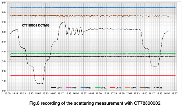
Note the excellent stability of the measurements even during fast temperature variations between 8°C and 22°C (lab temperature).
The sample mirror in this experiment is a slightly exposed clean mirror.
Accuracy scattering measurements
The high stability and repeatability of CT7 allows to perform scientific accuracy measurements of scattering. These measurements allow computing the true μrugosity of the sample.These measurements are obtained by repeating measurements at the same place using loop measurement . One can use a loop interval of 1 to 2 min; it is not recommended to go faster because of heating of the Leds; but one can experiment the fastest loop interval that yields stable results (there is no risk of damaging the source).
Table 10 shows CT7 measurements of a sample with 0.56 nm μ-roughness as measured with a Zygo interferometric instrument.
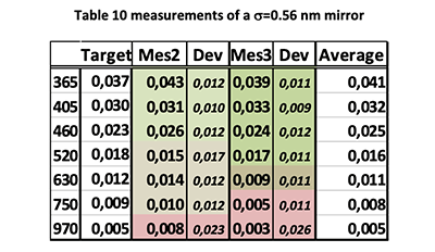
The first column gives the wavelength band, the second, the target measurement corresponding to the true μ-roughness of the sample mirror, the third is the average of 36 measurements made at 1 min intervals, the fourth is the standard deviation of the 36 measurement; the next two columns are the results of a repeated cession of 36 measurement and the last is the general average of the 72 measurements.
The relation between TIS (measured by CT7 ) and σ is :
TIS = (4.π.σ/λ)
2
Copyright:
Author:
Daniel Malaise, Dr Sc
First issue: October 2019
Last review: January 2021
This document is the sole property of OPO and, except to learn about our work, may not be used without our written consent.