Content:
Application note #7
Measurement of curved mirrors with CT7 and CT7a
To properly print this text, please download the file. You can easily do so using the Download button at the top right ↗️
Thank you for your interest!
Application note #7
Measurement of curved mirrors with CT7 and CT7a
Copyright:
Author:
Daniel Malaise, Dr Sc
First issue: November 2009
Last review: November 2020
This document is the sole property of OPO and, except to learn about our work, may not be used without our written consent.
This note deals with the sensitivity of reflectivity measurements to the curvature of the measured mirror with CT7 and CT7a .
With the CT7 instrument
We have shown in Note 5 and in previous papers that it is important to reduce the acceptance angle of the apparatus in order to measure the true specular reflectivity and reject as much as possible the scattered light close to the specular beam.
By doing this, one must ensure that the normal to the measured mirror is well co-aligned with the optical axis of the reflectometer; this is provided by the three point definition of the measuring plane. These are factory adjusted in order to realize a perfect alignment.
Another question arises when reducing the acceptance angle: the dioptric power of the sample mirror will change the focus of the test beam and the dimension of the beam inside the field acceptance stop. The purpose of this paper is to provide quantitative data about this problem.
We have traced through the system varying the curvature of the sample mirror between zero curvature (plane surface) and +/- 3.3e-4 mm-1 corresponding to a radius of +/- 3000 mm. Negative values correspond to convex mirrors.
The results are shown in the following graph.
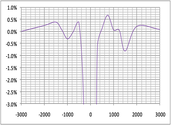
The plotted error is the difference between the value measured on a flat sample with 100% reflectivity and the same sample with a radius of curvature indicated by the X-axis.
One can see that the error is less than 0.5% for R<-500 (CX) and R>300 (CC). Moreover, this is a systematic deviation, and the graph can be utilized for applying a correction to the measurements if needed.
One should remember, however, that these are computed errors obtained by ray tracings through a perfect CT7 . It is recommended not to use CT7 under 1 m radius of curvature.
Alternatively, one can calibrate the actual corrections curve using flat sample mirrors coated in the same batch.
With the CT7a instrument
The point of incidence of the measuring beam (optical center) of the CT7a does not coïncide with the mechanical center (center of the inscribed circle of the three feet).
When measuring a curved mirror, the normal of the mirror at the optical center is not parallel to the optical normal of the instrument ; this angle, we call the curvature deflection angle. This angle is negligible for large mirrors with radius of curvature larger than 5m but becomes a source of error when getting smaller and smaller, as will be illustrated in the following.
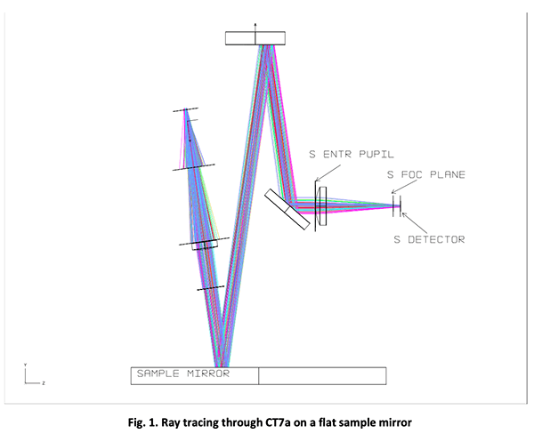
Fig. 1. Shows the ray tracing path through the CT7a on a flat sample mirror. In the following, we examine the image of the seven sources in the signal entrance pupil (S ENTR PUPIL) and in the Signal focal plane (S FOC PLANE). The signal on the signal detector (S DETECTOR) has always more margin than the same on the detector and is not shown on the following illustrations.
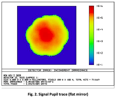
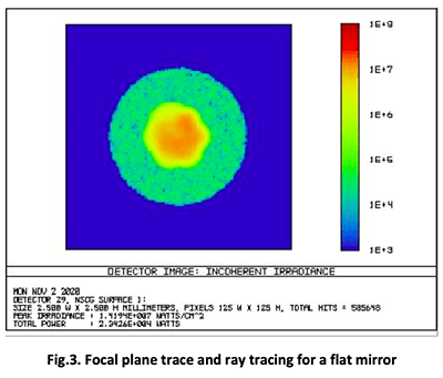
Fig.2. shows the trace of the bundle in the signal entrance pupil; the free pupil clearance is a little smaller than the blue square; it will appear clearly when pupil vignetting sets in (from fig.6. on).
In Fig.3. the green circle is the field acceptance diaphragm.
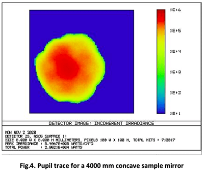
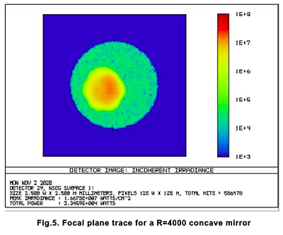
The following two figures (4 and 5) show the pupil trace and the focal plane trace for a 4000 mm radius concave mirror. The detector trace is not shown because it has always more margin than the focal plane trace.
One can observe that the pupil trace is just tangent to the pupil circle : it is already marginal, because in real world, there are other misalignments that will shift the beams slightly in various directions.
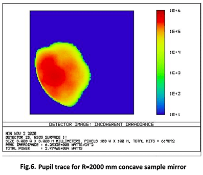
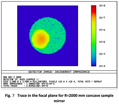
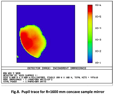
The following figures illustrate the casd of a 2000mm radius concave mirror; this is the usual range of radius for a laboratory 20 to 30 cm concave mirror. One sees, on Fig.6. that the beam is heavily vignetted by the pupil rim.
It is also important to notice that, the beams of the seven sources are clearly separated and that the vignetting can dim one to three channels and leave the others free of vignetting. This effect will vary with the specific instrument because when fabricating the sources, we do not control the order of fibers assembly in the final ferule.
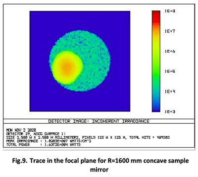
For a shorter radius mirror, the situation is worse, and one can expect that only one or two channels will yield correct results; The pupil vignetting is very large and is starting to grow in the focal plane although less severely.
Copyright:
Author:
Daniel Malaise, Dr Sc
First issue: November 2009
Last review: November 2020
This document is the sole property of OPO and, except to learn about our work, may not be used without our written consent.